1.5 The project in this manual
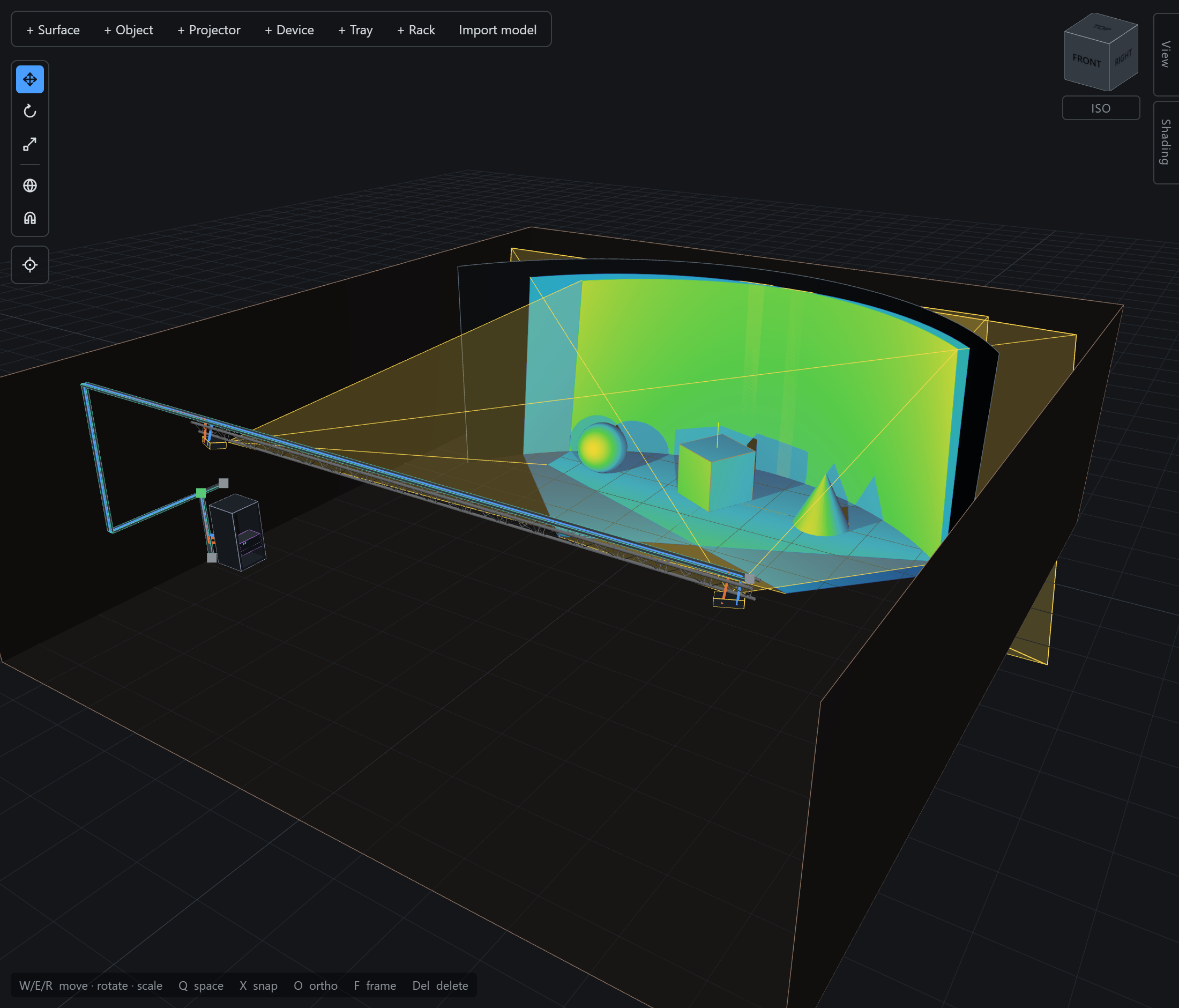
Figure 1.5 shows a small venue built so that there is something real to point at. It is worth reading once:
| Element | What it is |
|---|---|
| Room | A room object, 12 × 4 × 13.1 m — floor and three walls, open at the top |
| Curved screen | A curved surface, 12 m of screen bent on a 5.7 m radius, across the far end |
| Box / sphere / cone | Three objects standing on the floor in front of it, so the beams have something to fall across |
| Two Epson CO-FH01 | 3 000 lm, 1920 × 1080, each on its built-in 1.19 : 1 lens, both onto the curved screen |
| Trusses | Eight 1 m truss sections in a row, spanning the width of the room |
| Rack | A 22 U rack holding two players and a switch |
| Cable tray | One tray network — 16 m of run bent through four stretches |
| Four cables | Two HDMI, a player to each projector, and two Ethernet from the switch — all four routed through the tray |