7.8 The table, the fit and the review
Step 3 is where the paperwork gets typed. Working from switches between A distance table and I know the throw ratio — the second for when the number is simply published, and it takes the ratio at both ends of the zoom, the park, the shift travel as typed percentages, and the casting’s sections. Lengths in opens on millimetres, because that is what a drawing prints; switching converts what you have already entered rather than reinterpreting it.
Above the columns is a drawing of the machine with the run each column names dimensioned on it. Point at a header — or land in one of its cells — and that run lights up. It is schematic and never to scale: the question it answers is which run is this, not how long. The faces a distance can be measured to carry clickable markers, the chosen one solid, so Distance measured to can be answered on the drawing instead of in the dropdown.
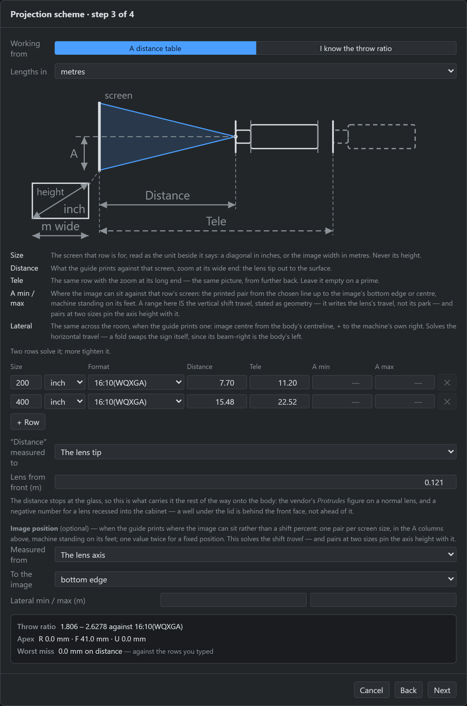
Two rows solve it; more tighten it. Two points fix a line and nothing fewer does — one row cannot separate a machine that throws wide from one that stands closer.
Worked example — an ET-D75LE20 on a PT-RQ13K, from the vendor’s calculator
| Rows (16:10, metres, to the lens tip) | 200″ → 7.70 · tele 11.20 · 400″ → 15.48 · tele 22.52 |
| Solved throw ratio | 1.806 – 2.6278 |
| Solved apex, past the front face | 41.0 mm |
| Worst miss | 0.0 mm |
| The catalogue’s own entry | 1.806 – 2.6278, apex 37.8 mm |
The throw ratio lands exactly on the shipped one, and the apex 3 mm past it. That 3 mm is the calculator’s own two-decimal printing: the same rounding on both rows is a constant, and a constant moves the datum rather than bending the line — which is why the fit can miss the rows you typed by nothing at all and still sit three millimetres from the entry the same lens ships with.
The readout shows the throw ratio, the solved apex, the shift where the columns solve one, and the worst miss in millimetres — how far the fitted line sits from the rows you typed.
Next is gated on a fit existing, not on it being good. A large miss is evidence, and it usually diagnoses one thing: the guide measures to a different face from the one you picked. Blocking would hide the very number that tells you so — move the datum and watch it collapse. The example above is the same story in miniature: had those rows been read to the front face instead of the lens tip, the apex would have landed 80 mm inside the machine, with the worst miss still reading zero.
The same step, the other three shapes
Step 2’s card is not a label — it is what this step becomes. Each family gets the drawing its own guides are printed against, the columns those guides carry, and the datums that make sense of them. Below is the step as it opens for the other three, before a row is typed.
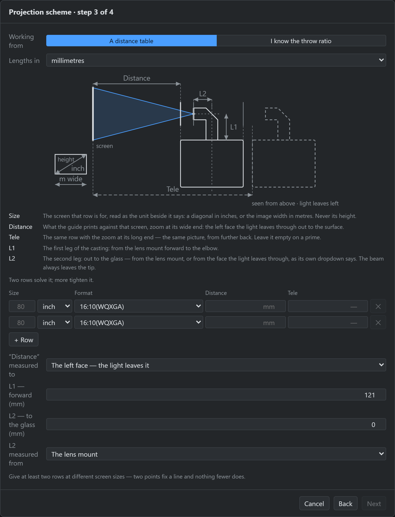
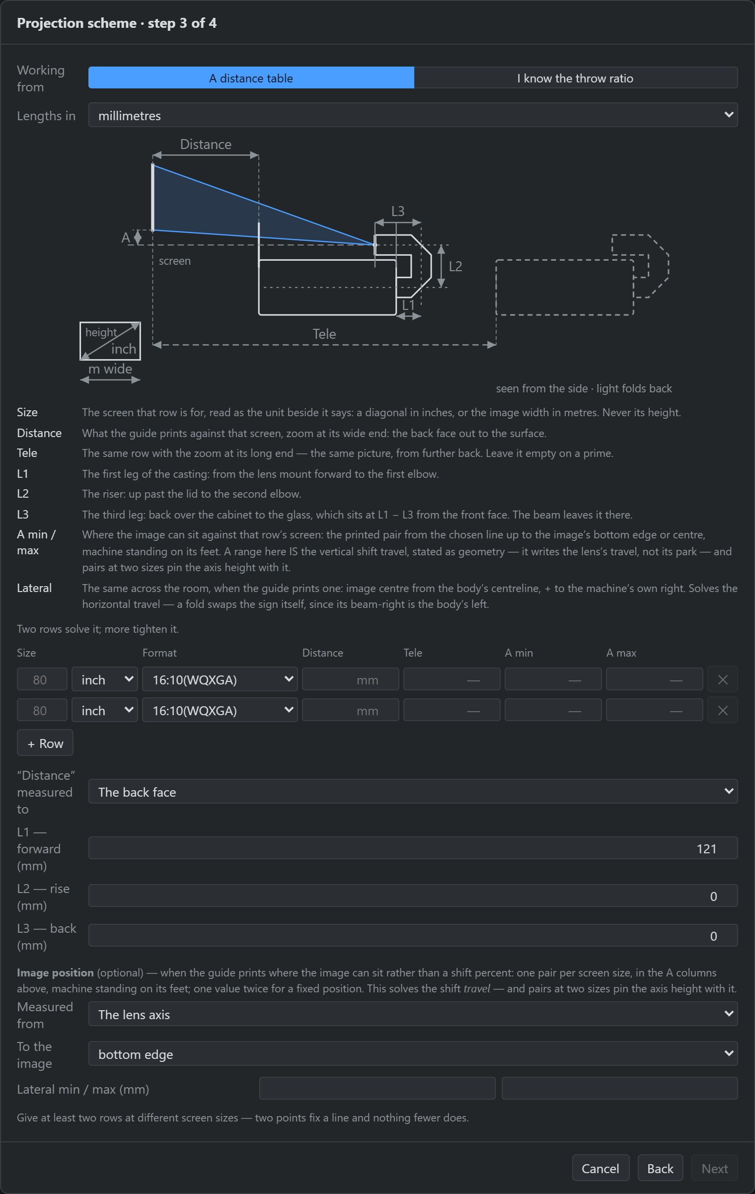
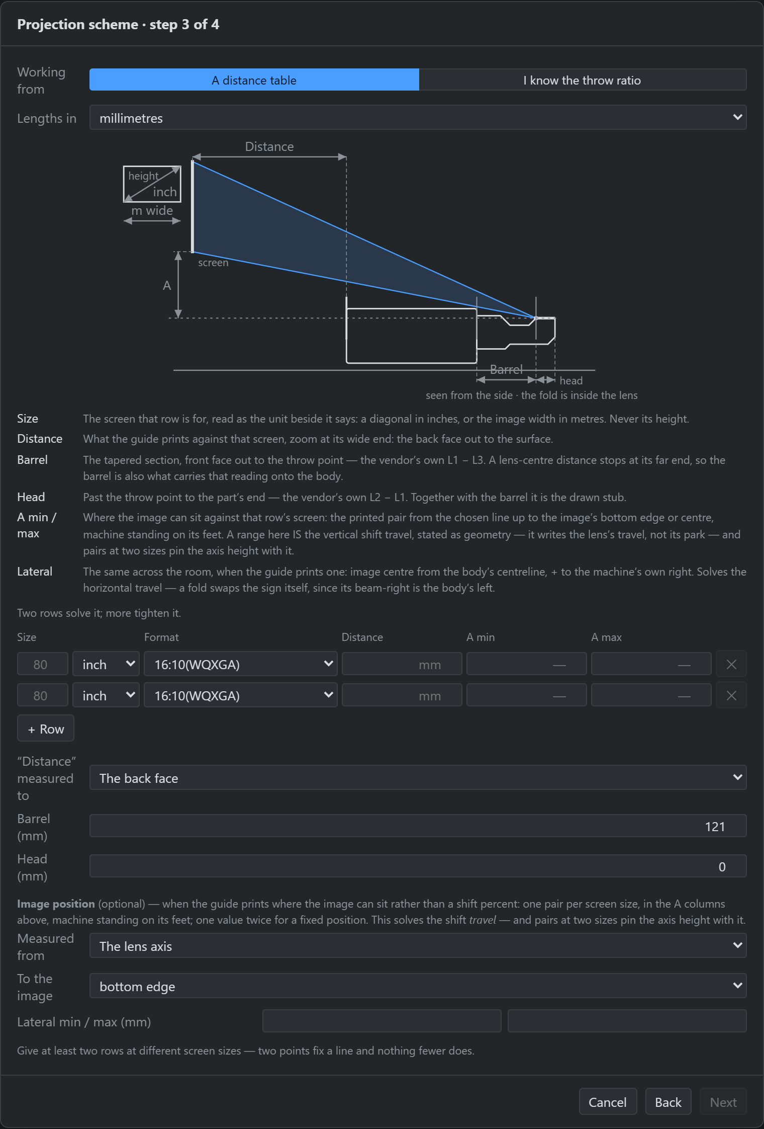
Two of those differences are worth stating as rules, because they decide which figure on a datasheet you are looking at:
- Typed sections are the authority. The casting is what you typed, the beam is derived from it, and the rows contribute the throw ratio, the zoom walk and a cross-check. Where the rows put the throw point somewhere the legs do not, the disagreement is reported in millimetres rather than resolved silently in either direction. It also retires a question: the fold’s legs and the bolt-on’s barrel already say where the glass sits, so those two are not also asked for a lens-from-front figure that could disagree.
- Drop and image position are two conventions for one thing. A welded-in ultra-short-throw is printed for an inverted wall mount and states the vertical as a drop from its own datum line — hence the Drop column and the Plate → datum figure that places that line on the machine. Everything else is printed standing on its feet and states the vertical as where the image can sit. Feeding one to the other reads the machine upside down, which is why a family is only ever shown its own.
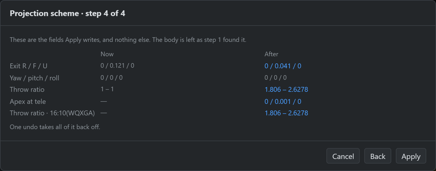
Step 4 reviews it. Two columns, Now and After, listing exactly the fields Apply will write and nothing else: the exit point, the rotation, the throw ratio and its per-format column, the apex at the long end of the zoom, the shift park and travel, and — above them, if step 1 staged any — the body rows.
Coefficients. Some vendors describe a lens as distance = a × diagonal + b, and it is
tempting to offer those two boxes — but no datasheet prints them. They live inside a
manufacturer’s online calculator, and every machine that has them already ships in the bundled
catalogue. That calculator answers “this size, this far” one size at a time, exactly as a printed
guide does, so its answers go in as table rows — measured to the lens, so set
Distance measured to to the lens tip — and recover the same optics. The
worked example above is precisely that: two calculator answers, and the lens comes back.