7.2 The Device tab
Device mode replaces both side panels: the left becomes the library of definitions this project owns, the right becomes the editor for the selected one.
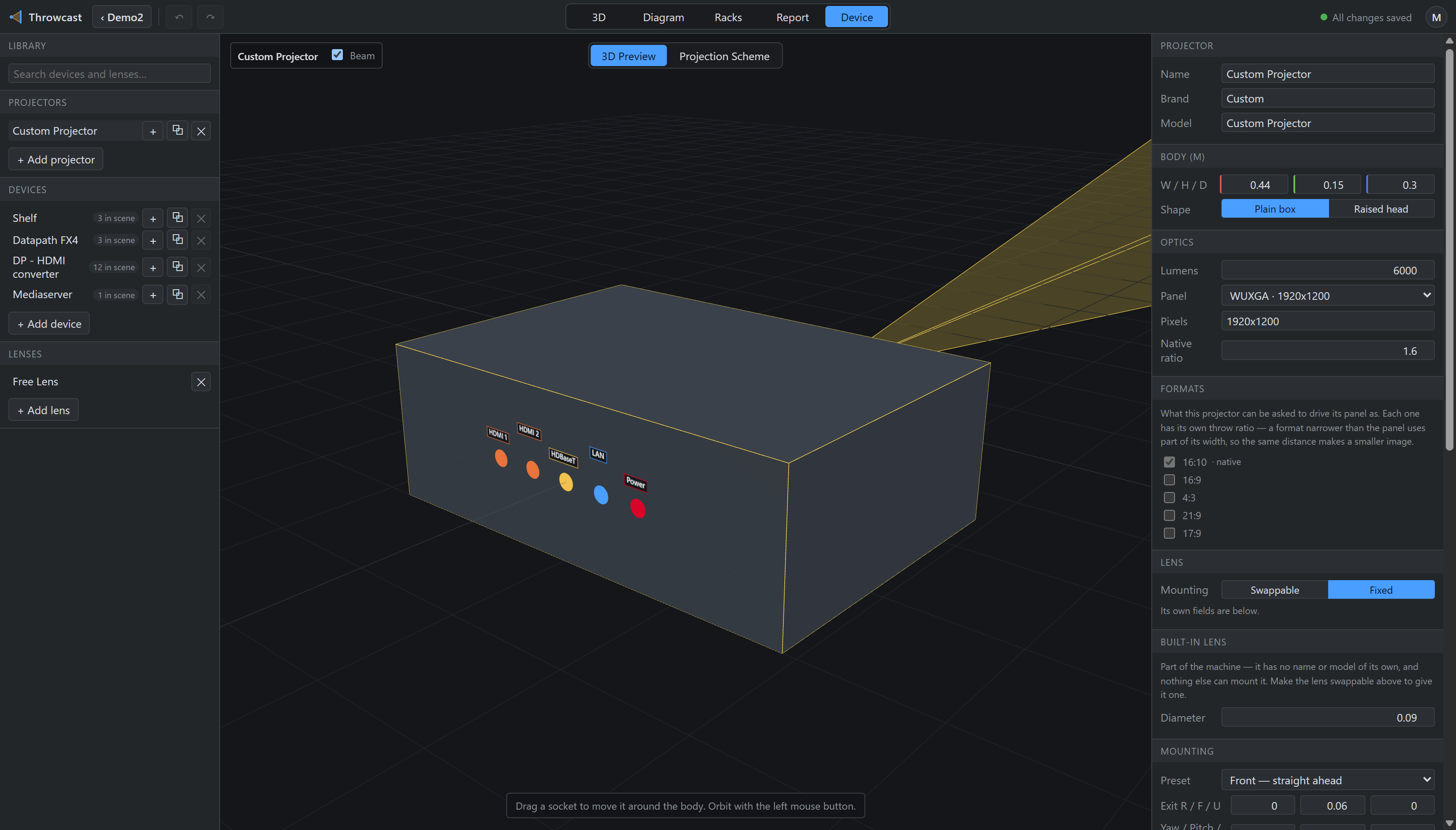
The editor covers the body (width, height, depth, and whether the machine wears a raised ultra-short-throw head), the optics (lumens, panel, native ratio), the image formats the panel can be driven in, lens mounting (fixed or swappable, and which lenses are compatible), and the ports.
A lens is authored as a casting: which of four shapes it is — a straight barrel, an elbow that turns the light 90°, a rear fold that throws back over the cabinet, or an ultra-short-throw — and how long each of its sections is. Where the beam starts and which way it leaves (§4.4) is derived from that, rather than typed as a set of offsets: say what the part is and the light leaves where the part says it does. Where it bolts on is the machine’s figure, not the lens’s — one Lens mount R / U on the body, so a lens that fits two chassis does not carry one of them around.
A projector does not have “an aspect ratio” — it has a panel and a list of formats it can drive
it in, and the throw ratio changes with the choice. Driving 4:3 on a 16:10 panel
uses only part of the panel’s width, so the same distance makes a narrower image and the ratio
rises by exactly panel ÷ chosen. Vendors tabulate a separate throw-ratio column per
format for this reason, and so does Throwcast.